Physical Layer
(Press ? for help, n and p for next and previous slide; usage hints)
Introduction
Core Questions
- What purpose does the physical layer serve in OSI network model?
- What is a frequency band for radio signal?
- How can we modulate a baseband signal to fit in the frequency band?
- What is the fundamental limit for reliable data transmission?
- How does multi-path deteriorate the communication channel?
- How to counter the multi-path effect using diversity?
- What considerations do we have for choosing PHY protocols?
Learning Objectives
- Definition of physical layer in the OSI network model
- Frequency band of radio signal
- Digital modulation and demodulation
- The capacity of a AWGN channel
- Coherence bandwidth and time due to multi-path
- Time/Space/Frequency diversity
- Various communication protocols and the comparison between them
Table of Contents
Overview
OSI 7-Layer Network Model
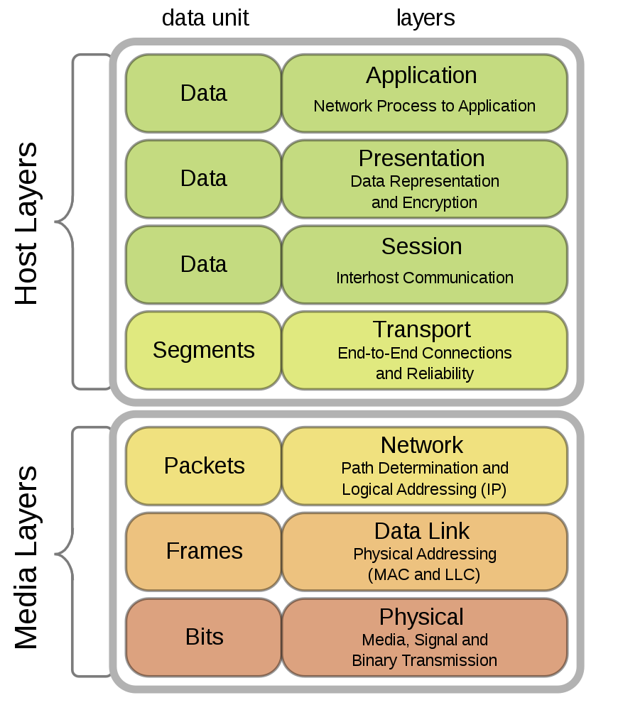
OSI Physical Layer
- The physical layer defines the means of transmitting raw bits over a physical data link connecting network nodes.
- Deals with accessing the physical medium
- Mechanical characteristics
- Electrical characteristics
- Functional characteristics
- Procedural characteristics
Wireless PHY protocols
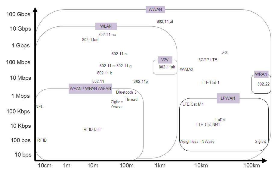
Various wireless communication protocols and categories designed for different ranges, data rates, and use cases
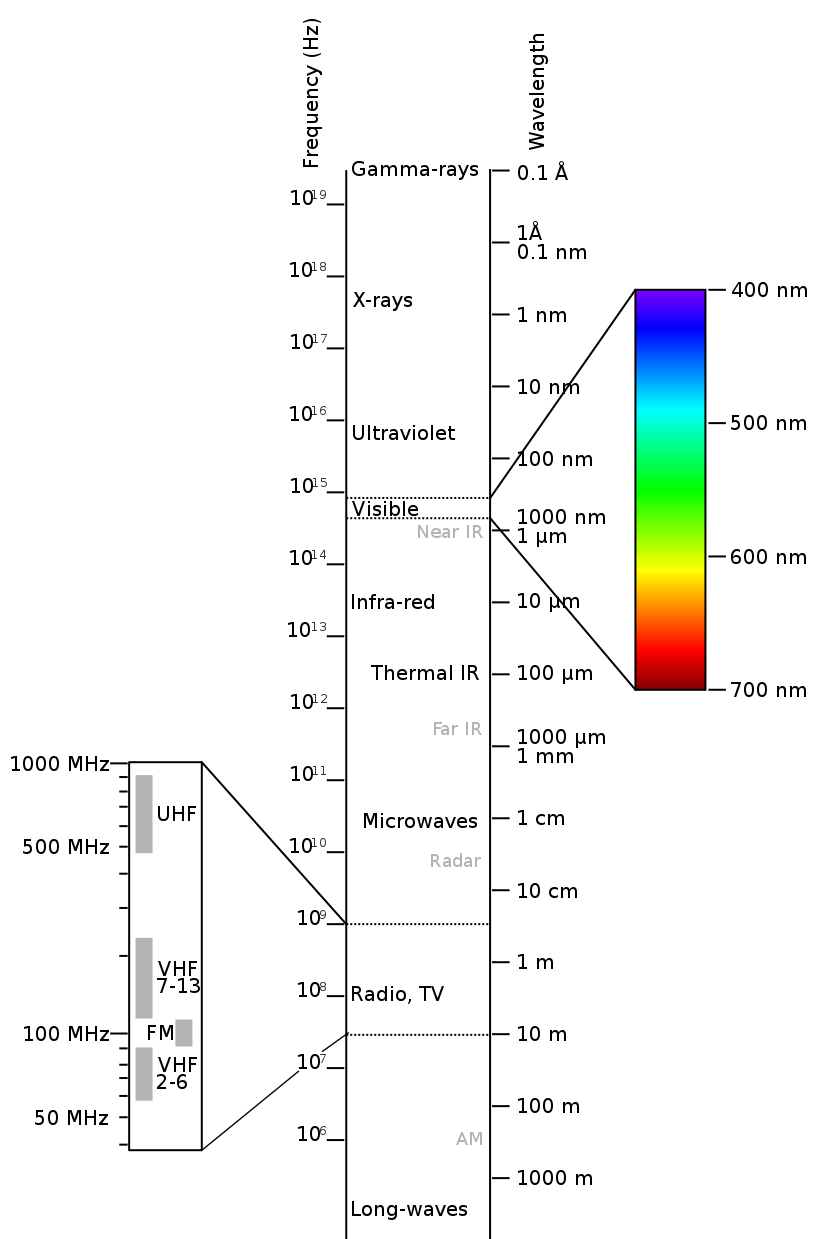
Electromagnetic Spectrum
Radio Frequency (RF) Signal
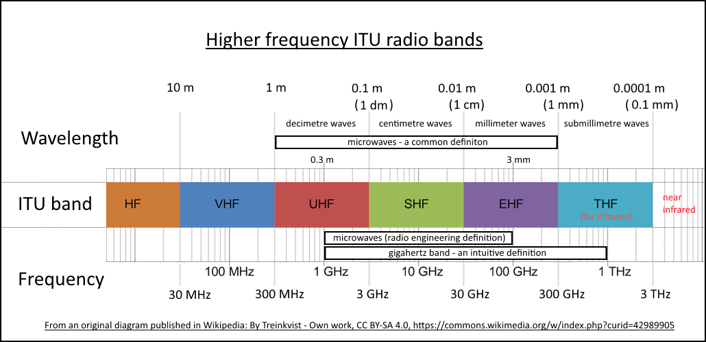
Frequencies and wavelengths of upper ITU radio bands with related common names
by Hedles under CC BY-SA 4.0; from Wikipedia
RF Band Allocation
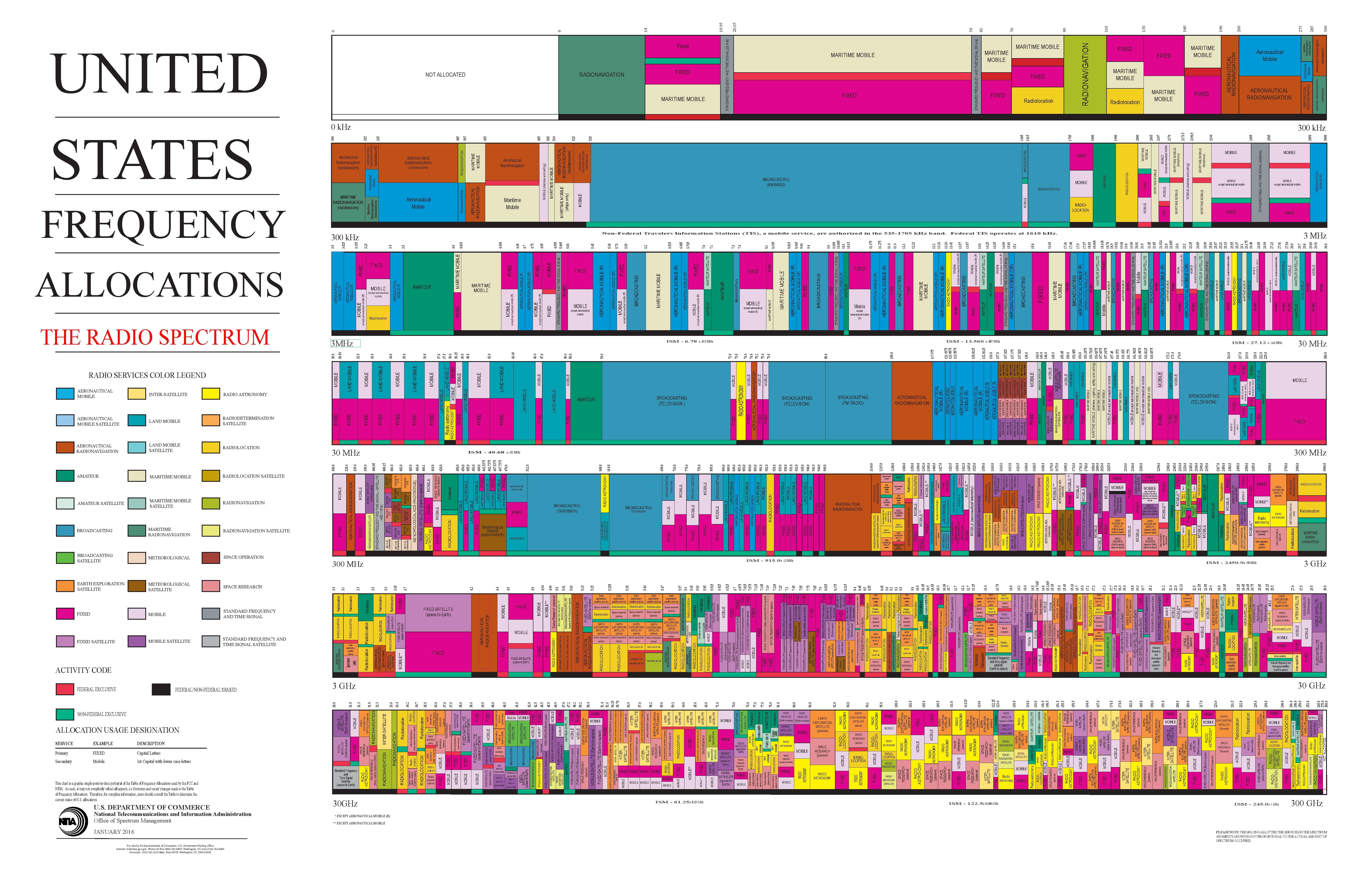
United States radio spectrum frequency allocations chart as of January 2016
by United States Department of Commerce under Public Domain; from Wikipedia
- Frequency band is a very rare & important resource!
ISM Band
- Radio spectrum reserved internationally for industrial, scientific and medical (ISM) purposes
- e.g., microwave ovens
- Fastest-growing use for low power wireless communications systems
- e.g., WiFi, Bluetooth, Zigbee, LoRa
- Communications equipment must tolerate interference generated by ISM applications
| Frequency Range | Center Frequency | Bandwidth | Availability |
| 433.05~434.79 MHz | 433.92 MHz | 1.74 MHz | Region 1 |
| 902~928 MHz | 915 MHz | 26 MHz | Region 2 |
| 2.4~2.5 GHz | 2.45 GHz | 100 MHz | Worldwide |
| 5.725~5.875 GHz | 5.8 GHz | 150 MHz | Worldwide |
Digital Modulation and Demodulation
Modulation Overview
- Modulation is the process of varying one or more properties of a periodic waveform, called the carrier signal, with a modulating signal that typically contains information to be transmitted.
- In digital modulation, an analog carrier signal is modulated by a discrete signal.
- The most fundamental digital modulation techniques are based on keying:
- ASK (amplitude-shift keying): a finite number of amplitudes are used.
- FSK (frequency-shift keying): a finite number of frequencies are used.
- PSK (phase-shift keying): a finite number of phases are used.
- QAM (quadrature amplitude modulation): a finite number of at least two phases and at least two amplitudes are used.
Rectangle and Sinc Function
- The simplest digital signal is a rectangle function:
\[rect(x) = \begin{cases} 1 & x \in [-0.5,0.5]\\ 0 & otherwise \end{cases}.\]
- Fourier Transform:
\[F(\omega ) = \int_{-\infty}^\infty f(t) \exp(2\pi i \omega t)dt.\]
- The FT of rectangle function is (normalized) sinc function
\[sinc(\omega) = \frac{\sin(\pi*\omega)}{\pi*\omega}.\]
Rectangle and Sinc Function
Energy Spectrum of Rectangle Function
- Most of the energy are located inside the passband of \(\pm 1Hz\).
Properties of Fourier Transform
| Time Domain | Frequency Domain | |
| Linear Combination | \(a\times f(t)+b\times g(t)\) | \(a\times F(\omega)+b\times G(\omega)\) |
| Multiplication | \( f(t)\times g(t) \) | \(F(\omega) * G(\omega)\) |
| Delay | \(f(t-\tau)\) | \(\exp(-2\pi i \tau \omega) F(\omega)\) |
Modulation
- If we multiply the baseband signal (\(rect(t)\)) with a carrier signal (\(cos(2\pi f_0 t)\))
\[S(t) = rect(t)\times \cos (2\pi f_0 t). \]
- In frequency domain, the signal will be centered around the carrier frequency \(f_0\)
- Most of the energy is allocated inside \(f_0\pm 1\).
- If we reduce the symbol time from \(1s\) to \(\tau s\):
- The modulated signal will still be centered around \(f_0\)
- However, the zero crossing will happen at \(f_0 \pm 1/\tau\).
Modulation
Demodulation
- The baseband signal can be recovered as
- A low pass filter can be used in order to:
- Filter out the high frequency \(rect(t) \times \cos(4\pi f_0 t)\) component;
- And recover the baseband signal \(rect(t)\).
Demodulation
Amplitude-Shift Keying
Amplitude-Shift Keying
- We are allocated with a frequency band between 200-300kHz. If we use 4-ASK modulation scheme:
- What is the carrier frequency?
- What is the symbol rate per second?
- What is the bit rate per second?
Frequency-Shift Keying
Frequency-Shift Keying
- In practice, we can smooth the digital signal
- e.g., by Gaussian filter
- the frequency changes more smoothly rather than instantaneously
- to reduce sideband power
- We are allocated with a frequency band between 200-300kHz. If we use FSK modulation scheme:
- What are the sub-carrier frequencies if we assume that we use two frequencies that are 10Mhz apart?
- What is the bit rate per second?
Phase-Shift Keying
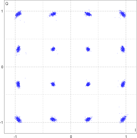
QAM
Constellation Diagram
- We could draw the amplitude and phase of the symbol on the complex plane:
Quadrature Amplitude Modulation (QAM)
- We could combine multiple amplitude and multiple phase together to form a constellation
- The most common ones are 16, 64, 256 QAM
- each symbol carries 4, 6, 8 bits repsectively
- For WiFi 6, up to 1024-QAM can be used depending on the channel quality
- Can we use “infinite”-QAM to transmit at “infinite” bit rate?
Free Space Propagation Model
Free Space Loss
Channel Impairments
- Free space loss
- Noise
- Fading
- Multi-path (Next Section)
- Atmospheric absorption
Free Space Transmission
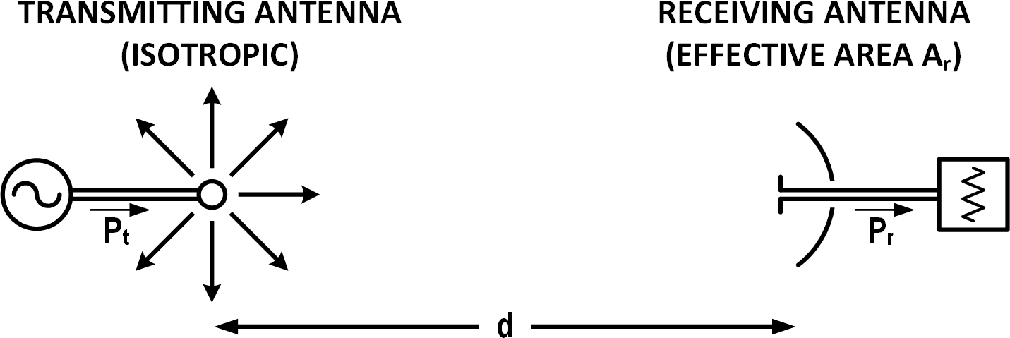
Friis Transmission Equation
- Friss Transmission Equation: \[\frac {P_r}{P_t}=D_rD_t\left(\frac {\lambda}{4\pi d}\right)^2.\]
- where:
- \(P_{t}\) is the power fed into the transmitting antenna input terminals;
- \(P_{r}\) is the power available at receiving antenna output terminals;
- \(D_{r}, D_t\) are the antenna directivities (with respect to an isotropic radiator) of the transmitting and receiving antennas respectively;
- \(d\) is the distance between antennas;
- \(\lambda\) is the wavelength of the radio frequency;
- Friss Transmission Equation: \[\frac {P_r}{P_t}=D_rD_t\left(\frac {\lambda}{4\pi d}\right)^2.\]
- To increase signal strength at the receiving end:
- Increase transmitting power;
- Decrease carrier frequency, distance;
- Better antenna
Noise
- Thermal Noise(John-Nyquist Noise)
- Noise seen in switching circuits due to electrons
- Inter-modulation noise
- Noise caused by signals at different frequencies on the same medium
- Crosstalk
- coupling between signal paths
- Impulse Noise
- Power spike (e.g. from thunder)
Thermal Noise
- White noise since it contains the same level of power at all frequencies \[N = ktB\]
- \(k\) is the Boltzmann’s constant: \(1.381\times 10^{-21} W/(K\cdot Hz)\),
- \(T\) is the absolute temperature in Kelvin, and
- \(B\) is the bandwidth.
- At room temperature, \(T = 290K\), the thermal noise power spectral density \(kT = –174 dBm/Hz\)
- dBm is the ratio between the power and a reference of one milliwatt (mW), expressed in dB.
- 0dBm = 1mW, 10dBm = 10mW, 20dBm = 100mW
- For 1MHz bandwidth, the power of the noise is
\(-174 + 10 log 1M= -114dBm\) or \(4\times 10^{-15}W\).
Thermal Noise
Constellation Diagram with Noise
Channel Capacity
Basic of Detection Theory
- Assuming we are using BPSK.
- At the receiving end, we get the following signals:
\[y = x + w = \pm a + w,\]
- \(a^2\) can be viewed as the energy of the received signal
- \(w\sim \mathcal N(0,N_0)\) is a zero mean Gaussian noise, with average energy \(N_0\)
- The Signal to Noise Ratio (SNR) can be defined as \(SNR = a^2/N_0\).
Probability of Error
- We need to estimate (“detect”) the phase of \(x\)
- The probability of error is
\[P_e = P(\hat x \neq x).\]
Bayesian Detector:
- Calculate the conditional probability
\begin{align*} P(x = a|y) &= \frac{P(x = a)P(y|x = a)}{P(y)},\\ P(x =- a|y) &= \frac{P(x = -a)P(y|x =- a)}{P(y)}. \end{align*}- If \(P(x=a|y)\geq P(x=-a|y)\), then \(\hat x = 0\), otherwise \(\hat x = \pi\).
Probability of Error
- Assuming \(\pm a\) has equal probability, then the decision rule is
\[\hat x = \begin{cases} 0 & if\;y\geq 0\\ \pi& otherwise\end{cases}.\]
- The probability of error is given by
Encoding/Decoding
- To reduce bit error rate, one could
- increase the SNR.
- However, this is very expensive
- More clever solution:
- We could transmit the same bit multiple times (repetition code)
- or better yet, use error correct code
- Problem: If we use “higher” QAM (assuming the same average signal energy)
- we pack more symbols into the same area in the constellation diagram
- the symbols are more difficult to differentiate -> higher error rate per symbol
- However, we could use better encoder to reduce the bit error rate
- Can we achieve infinite bit rate (under some constraints on bit error rate)?
Shannon-Hartley Theorem
\[C = B \times log_2( 1 + S/N ) = B \times log_2( 1 + SNR )\]
- where:
- \(C\) the information rate of data that can be communicated at an arbitrarily low error rate;
- \(B\) is the bandwidth of the channel in hertz;
- \(S\) is the average received signal power over the bandwidth measured in watts; and
- \(N\) is the average power of the noise and interference over the bandwidth, measured in watts.
- Fundamental limit: We CANNOT achieve a data rate higher than \(C\) regardless of modulation/encoding scheme.
- Achievability: For any data rate lower than \(C\), there exists a modulation/encoding scheme to achieve it.
- Problem: the computational complexity is usually very high
- Polar code is the first capacity-achieving code with complexity of \(O(n\log n)\).
Shannon-Hartley Theorem
\[C = B \times log_2( 1 + S/N ) \]
- What if we increase the bandwidth \(B\)?
- The noise \(N = kTB = N_0B\) will also increase!
- The maximum capacity is still bounded by \(\log_2(e) S/N_0 \approx 1.44 S/N_0\).
Shannon-Hartley Theorem
\[C = B \times log_2( 1 + SNR )\]
- Even SNR is very bad, we can still have reliable communication:
\[C = B \times log_2( 1 + SNR ) \approx \log_2(e) B \times SNR. \]
- Example: GPS communication
- \(B\): 1 MHz bandwidth,
- \(SNR\): −30 dB, the signal is 1000 times smaller than noise!
- \(C \approx 1.44\times 10^6 \times 10^{-3} = 1440 bit/s\)
- Navigation message of GPS is sent at 50 bit/s
- reliable communication can be established.
Implications
- Good physical layer protocol for intelligent networked system:
- Long Range
- High Throughput
- Low Power
- Other metrics: low latency, mobility, cost, …
- Shannon-Hartley Theorem & Friis transmission equation: NO communication scheme can achieve long range, high throughput and low power simultaneously.
- Need to consider applications:
- Surveillance camera for smart city: long range, high throughput
- Environmental monitoring: long range, low power
- Smart Building: short range
Multi-Path Problem
Multi-path
Impairments
- Free space loss
- Noise
- Fading
- Multi-path
- Atmospheric absorption
Multi-path
- Multi-path: obstacles reflect signals so that multiple copies with varying delays are received
- Reflection - occurs when signal encounters a surface that is large relative to the wavelength of the signal
- Diffraction - occurs at the edge of an impenetrable body that is large compared to wavelength of radio wave
- Scattering – occurs when incoming signal hits an object whose size in the order of the wavelength of the signal or less
Reflecting Wall Example [Tse2005]
- Assuming a single frequency \(f\) sinusoidal signal is transmitted
- The direct signal has a phase delay of
\[\phi_1 = \frac{2\pi}{c}rf.\]
- The reflected signal has a phase delay of
\[\phi_2 = \frac{2\pi}{c}(2d-r)f.\]
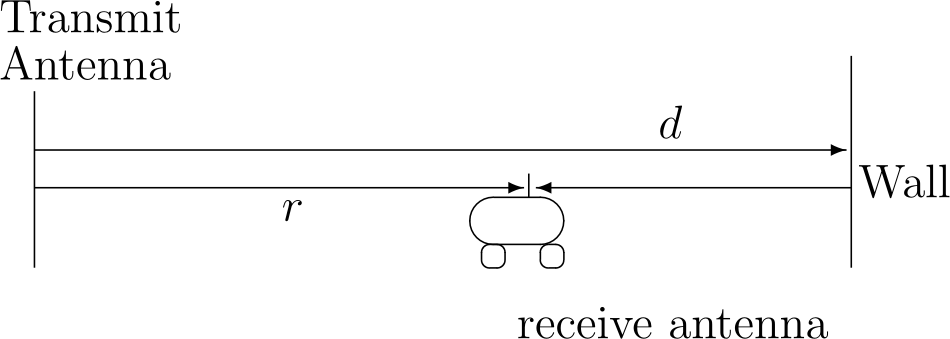
Reflecting Wall Example
- The phase difference of the two signal is \[\Delta \phi = \frac{4 \pi}{c} (d-r)f.\]
Coherence Bandwidth
- The difference between the max and min delay is called delay spread. In our case, \[T_d = \frac{2(d-r)}{c}.\]
- If the frequency changes by \(1/2T_d\), then the phase difference changes by \(\pi\).
- \(W_c = 1/2T_d\) is called coherence bandwidth.
- For cellular communication, the path length difference is usually less than 300m
- The delay spread is \(300m/c = 1\mu s\)
- The coherence bandwidth is \( (2 \mu s)^{-1} = 500 KHz\).
Flat v.s. Frequency Selective Fading
- Flat fading: \(W_c\) is much larger than the bandwidth of the signal.
- All frequency components of the signal will experience the same magnitude of fading.
- Narrowband signal: GSM use 200kHz sub-channel
- Frequency-selective fading: \(W_c\) is smaller than the bandwidth of the signal.
- Different frequency components of the signal experience different fading.
- Countermeasures: equalization, …
- Wideband signal: cdmaOne uses 1.25Mhz
Flat v.s. Frequency Selective Fading [Tse2005]
Impulse Response of a Fading Channel
Intersymbol Interference
- Delay causes copies of the signal arriving at the receiver at different times
- Part or all of a given symbol will be spread into the subsequent symbols
- Interfering with the correct detection of those symbols
- To avoid ISI, symbol duration needs to be much larger than delay spread
Coherence Time
- Recall that phase difference of the two signal is \[\Delta \phi = \frac{4 \pi}{c} (d-r)f.\]
- If the frequency is fixed, then the phase changes \(\pi\) if the receiver moves
\[\Delta r = c/4f.\]
- For a carrier frequency of 1GHz, \(\Delta r \approx 7.5 cm\).
- Consider we are on a vehicle at speed \(60km/h \approx 16.7m/s\)
- It takes 4.5ms for \(\Delta \phi\) to change \(\pi\)
- This time is called coherence time
Fading
- If we assume:
- the initial path length difference \(2(d-r_0) = 300m\);
- the base frequency \(f_0 = 1GHz\);
- moving speed of 10m/s.
Real World Fading
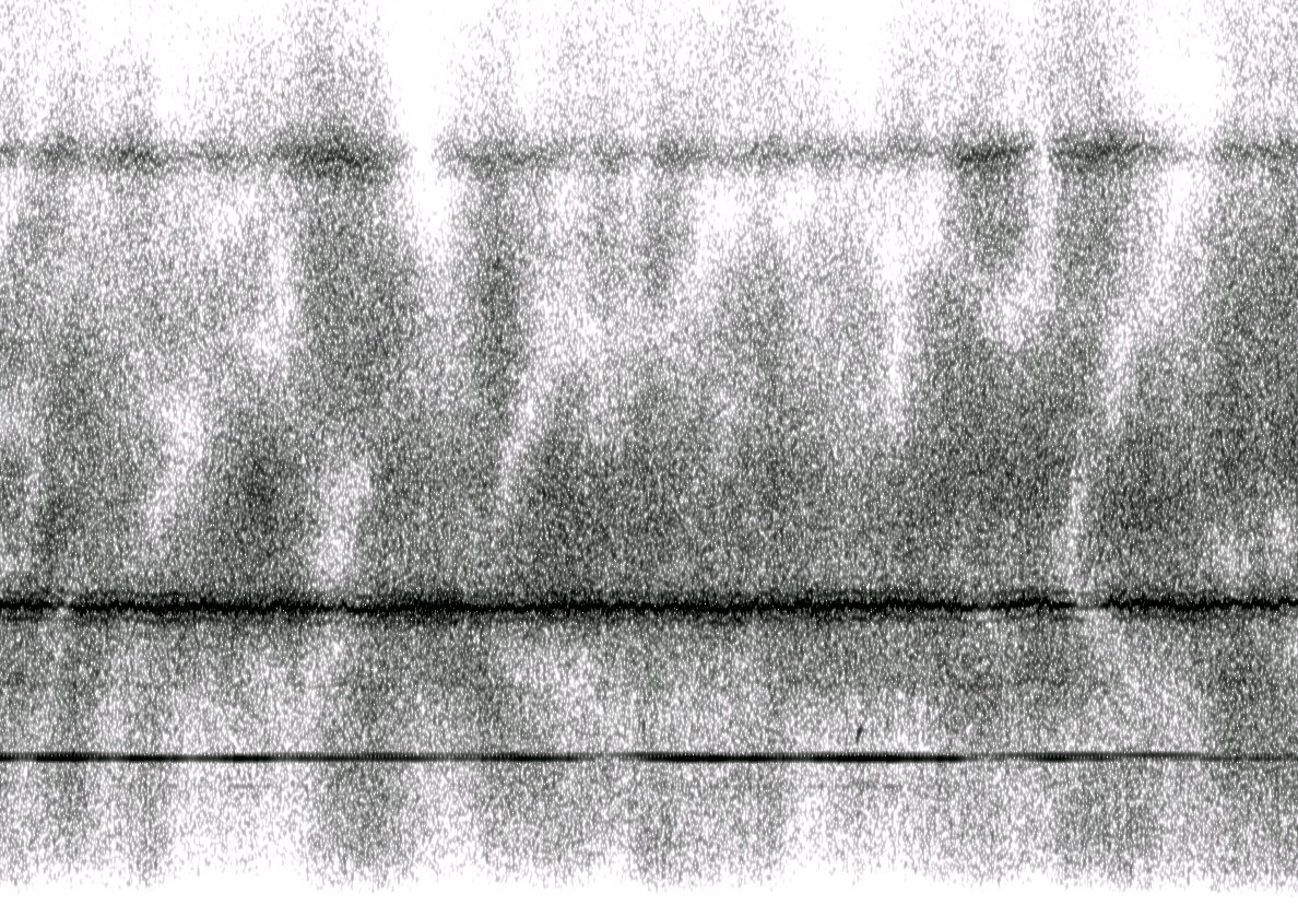
An unidentified radio signal at 6.600 MHz with strong propagation noise
by Mysid under Public Domain; from Wikipedia
Diversity
Time Diversity
- Wireless communication is usually an underspread channel
- Delay spread (\(\mu s\)) is much smaller than coherence time (ms)
- A narrowband signal (flat-fading) can transmit hundreds of symbols during a coherent time window
- To ensure that the coded symbols are transmitted through independent or nearly independent fading gains, we can interleave the code.
- Drawbacks: may results in large latency
- GSM use TDMA for voice communication
Time Diversity
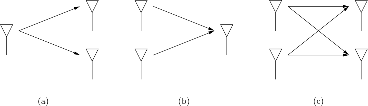
Space Diversity: MIMO
- Multiple antenna can be used at the transmitting and receiving end
- Instead of destructive fading, we can achieve constructive fading
![Figure]()
SIMO, MISO and MIMO
Frequency Diversity
Spread Spectrum
- Spread-spectrum: a signal with a particular bandwidth is deliberately spread in the frequency domain, resulting in a signal with a wider bandwidth.
- Benefits
- Frequency diversity: not all frequencies are in deep fade
- Used for hiding and encrypting signals
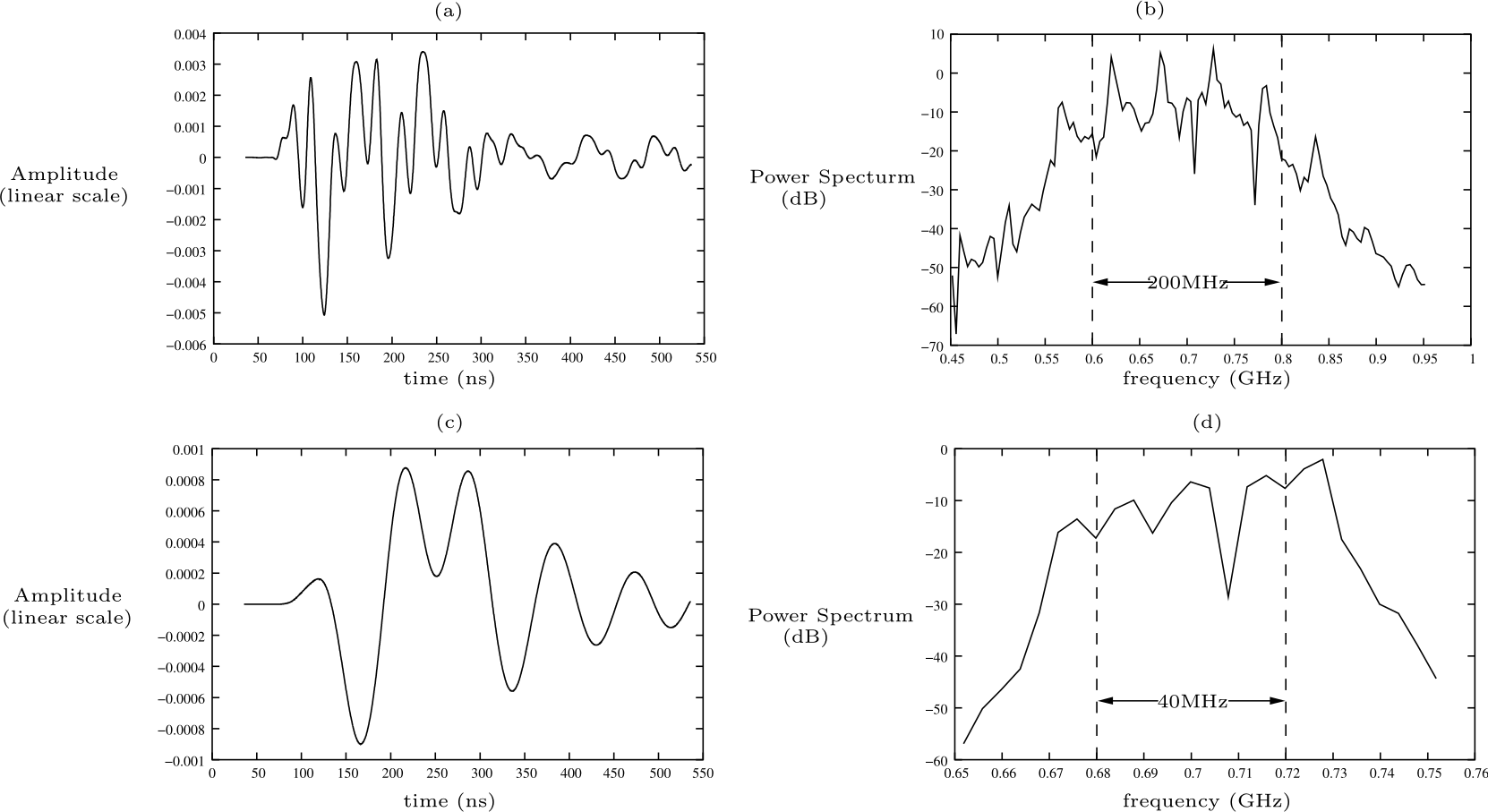
Chirp Spread Spectrum
- A chirp is a sinusoidal signal of frequency increase or decrease over time
- Idea for low energy communication protocols
- e.g. LoRa
Direct Sequence Spread Spectrum
- Information is encoded and modulated by a pseudonoise (PN) sequence
- The data rate \(R\) is much smaller than the transmission bandwidth \(W\) Hz
- e.g., cdmaOne use a bandwidth of 1.2288 MHz
- and a typical data rate (voice) is 9.6 kbits/s
- The processing gain is \(1228.8/9.6 = 128\)
- 64 chips are used for 1 data bit
Direct Sequence Spread Spectrum
- Assuming BPSK: 1 is coded as +1, and 0 is coded as -1
Direct Sequence Spread Spectrum: Decoding
- The original symbol can be recovered by performing an inner product with the same PN sequence
Direct Sequence Spread Spectrum
- How to combat Intersymbol interference:
- The shifted PN sequence is “orthogonal” to the original sequence
Frequency Hopping Spread Spectrum
- Frequency-hopping spread spectrum is a method of transmitting radio signals by rapidly changing the carrier frequency among many distinct frequencies occupying a large spectral band
- e.g. Bluetooth LE uses 37 channels, each occupy 2MHz
- Channels are switched at a rate of 1600 hops/s (\(625\mu s\)).
Orthogonal Frequency Division Multiplexing
- Consider the Bluetooth LE example
- Assuming a symbol rate of \(R\)
- The corresponding \(sinc\) function will occupy \(2R\) bandwidth
- Hence, \(2R + guard\;band\leq 2MHz\)
- Is it really necessary?
Orthogonal Frequency Division Multiplexing
Orthogonal Frequency Division Multiplexing
- \(sinc(x + k),\, k\in\mathbb Z\) are orthogonal to each other
- For the OFDM scheme
- If the symbol rate is \(R\)
- Each sub-carrier signal only needs to be \(R\) apart
- More than twice spectral efficient
- Modulation/Demodulation can be done efficiently via Fast Fourier Transform
- OFDM is originally proposed by Bell lab in 1966
- Used in WiFi, 4G, 5G
Physical Layer Protocol
Bluetooth LE
Bluetooth is a low-power wireless connectivity technology
![Bluetooth Logo]()
“Bluetooth Logo” by Skarr21 under CC BY-SA 4.0; from Wikipedia
- cell phones sensors
- headsets
- keyboards/mouses
- video game systems
- The name Bluetooth refers to King Harald Blatand in the region of what is now Norway and Sweden in around 958AD.
- He got this name due to his liking of blueberries and/or the eating of his frozen enemies.
- Bluetooth is derived from his name because King Blatand brought together warring tribes.

Bluetooth LE
- Bluetooth Low Energy is used extensively in IoT deployments
- beacons
- wireless sensors
- asset tracking systems
- remote controls
- health monitors
- and alarm systems.
- Throughout its history, Bluetooth and all the optional components have been under GPL license and are essentially open source.
PHY of Bluetooth LE
- Operates in the 2.400–2.4835 GHz ISM band (Same as WiFi and 802.15.4)
- The ISM band is divided into forty 2-MHz channels.
- 37 of the channels are used to transmit date
- 3 channels are reserved for advertising
- frequency hopping is used to provide diversity
- Within a channel, data is transmitted using Gaussian FSK modulation
- The bit rate is 1 Mbit/s, and the maximum transmit power is 10 mW
- Can be increased to 2Mbit/s and 100 mW in Bluetooth 5
PHY of Bluetooth LE [Lea2018]
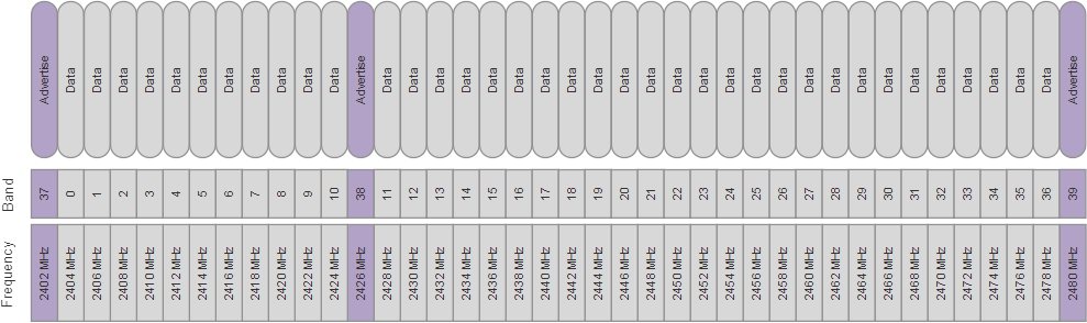
Bluetooth Low Energy Channels
Comparison between Bluetooth and Bluetooth LE
| Technical specification | Bluetooth | Bluetooth Low Energy technology |
| Distance/range (theoretical max.) | 100 m | <100 m |
| Over the air data rate | 1–3 Mbit/s | 125k – 500k – 1M – 2 Mbit/s |
| Power consumption | 1 W as the reference | 0.01–0.50 W (depending on use case) |
| Peak current consumption | <30 mA | <15 mA |
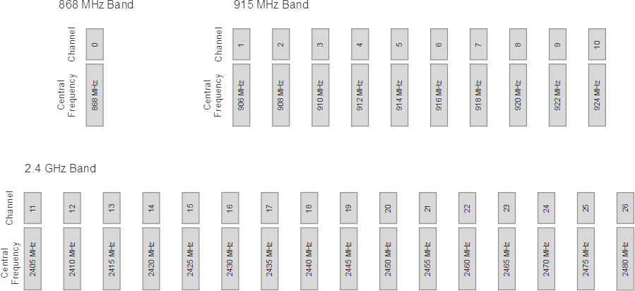
IEEE 802.15.4
- The IEEE 802.15.4 is a standard wireless personal area network (PAN) defined by the IEEE 802.15 working group.
- Defines the physical and MAC layer
- basis of many other protocols: Thread, Zigbee, WirelessHART, and others.
- The goal is to develop a low-cost WPAN with low power consumption.
- Operates in the ISM spectrum:
- 868 MHz, 915 MHz, and 2400 MHz.
| Frequency range (MHz) | Channel numbers | Modulation | Data rate (Kbps) | Region |
| 868.3 | 1 channel: 0 | BPSK/O-QPSK/ASK | 20/ 100 /250 | Europe |
| 902-928 | 10 channels: 1-10 | BPSK/O-QPSK/ASK | 40/250/250 | North America, Australia |
| 2405-2480 | 16 channels: 11-26 | O-QPSK | 250 | Worldwide |
PHY of IEEE 802.15.4 [Lea2018]
- Direct Sequence SS/Chirp SS/Ultra-wideband can be used for diversity
- Typical range: 200 meters outdoors, 30m indoors
Typical transmission current: 15~30 mA, and reception current: 18~37mA
![Figure]()
Bluetooth Low Energy Channels
IEEE 802.11 (WiFi)
- First release in June 1997
- The newest is WiFi 6
- Works in both 2.4Ghz and 5Ghz ISM band
- Support up to 1024-QAM
- Use OFDMA for spreading spectrum and multiple user access
- Use Multi-user MIMO
WiFi Channels
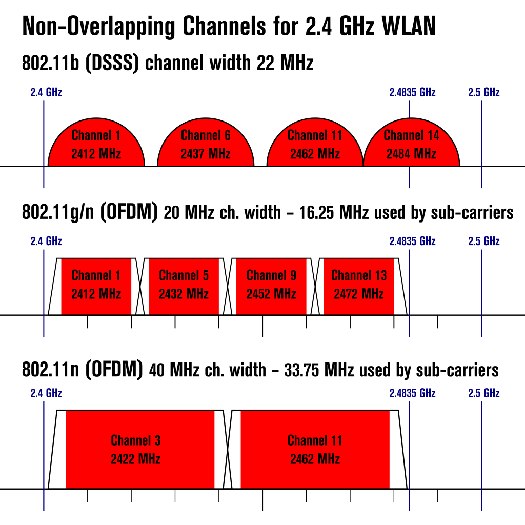
Non-overlapping 2.4GHz Wireless LAN Channels
by Liebeskind under GNU Free Document License; from Wikipedia
WiFi MIMO [Lea2018]
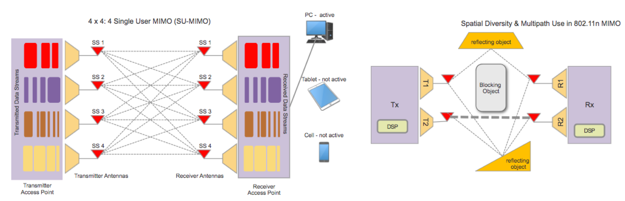
Single User MIMO for 802.11n
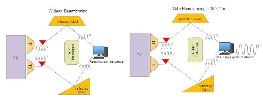
Beamforming for 802.11n
Comparison between different generations of WiFi
| Generation | Release | Frequency(GHz) | BW(MHz) | Modulation | Diversity | MIMO | Max Mbps |
| b | 1999 | 2.4 | 22 | QPSK | DSSS | 1 | 11 |
| a | 1999 | 3.7/5 | 20 | 64-QAM | OFDM | 1 | 54 |
| g | 2003 | 2.4 | 20 | 64-QAM | OFDM/DSSS | 1 | 54 |
| n | 2009 | 2.4/5 | 20~40 | 64-QAM | OFDM | SU: 4 | 150 |
| ac | 2013 | 5 | 20~160 | 256-QAM | OFDM | MU: 8 | 867 |
| ax | 2019 | 2.4/5 | 20~160 | 1024-QAM | OFDMA | MU: 8 | 1000 |
Cellular Communication
- The International Telecommunication Union (ITU) is a UN specialized agency
- was founded in 1865
- took its present name in 1932
- before becoming a specialized agency in the UN.
- the Radio communication Sector (ITU-R) defines the international standards and goals for various generations of cellular communication.
| 2G | 3G | 4G | 5G | |
| First Availability | 1999 | 2002 | 2010 | 2020 |
| Bandwidth | NA | Stationary: 2Mbps Mobile 384Kbps | Stationary:1 Gbps, Mobile 100Mbps | Min Down: 20 Gbps/ Min Up: 10 Gbps |
| Features | Voice, SMS | Audio, Video | Unified IP and seamless LAN/WAN/WLAN | IoT, ultra density, low latency |
5G Scenarios
- Enhanced Mobile Broadband (eMBB):
- 1 to 10 GBps connections to UEs/endpoints in the field (not theoretical)
- 100% coverage across the globe (or perception of)
- 10 to 100x the number of connected devices over 4G-LTE
- Connectivity at a speed of 500 km/h
- Ultra-Reliable and Low-Latency Communications (URLLC):
- Sub < 1 ms end-to-end round-trip latency
- 99.999% availability (or perception of)
- Massive Machine Type Communications (mMTC):
- 1000x bandwidth per unit area; this implies roughly 1 million nodes in 1 km 2
- Up to a 10 year battery life on endpoint IoT nodes
- 90% reduction in network energy usage
Sub-6 and mmWave
- 4G-LTE systems mainly use frequencies <3 GHz range.
- 5G may use a multitude of frequencies:
- Sub 6 GHz: More ready for immediate use
- China Telecom: 3.4-3.5MHz
- China Unicom: 3.5-3.6MHz
- China Mobile: 4.8-4.9MHz
- mmWave (30-60 GHz): High bandwidth available, Gbps throughput
- Higher free space loss
- Absorbed by the atmosphere, vegetation, human body
- Difficult to penetrate walls
- Solution: Massive MIMO
- Sub 6 GHz: More ready for immediate use
LoRa
- LoRa is a physical layer for a long-range and low-power IoT protocol
- Originally developed by Cycleo in France and then acquired by the Semtech Corporation in U.S.
- ZTE and Alibaba are in the LoRa Alliance.
- Uses the following ISM band:
- 915 MHz: In the USA
- 868 MHz: In Europe
- 433 MHz: In Asia.
- Chirp Spread Spectrum (CSS) is the modulation technique used in LoRa.
- Typical data rate is 0.3 - 5kbps
- Each LoRa packet contains 51-222 Bytes of Data
- Typical Energy for one message is < 1 \(\mu Ah\)
- Typical range of communication is 2-3km in cities and 5-7km in rural area
- The world record is 702km!
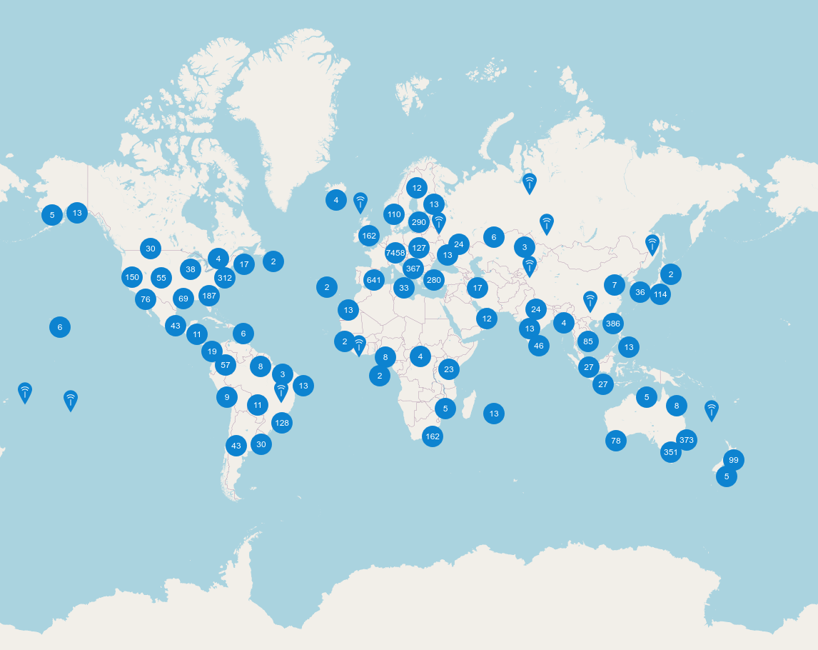
The Things Network
15669 gateways in 150 countries as of Oct, 2020
![Figure]()
LoRa Gateways
Comparison
- Good physical layer protocol for intelligent networked system:
- Long Range
- High Throughput
- Low Power
- Other metrics: low latency, mobility, cost, …
- NO communication scheme can achieve long range, high throughput and low power simultaneously.
- Need to consider applications:
- Surveillance camera for smart city: 4G/5G
- Environmental monitoring: LoRa
- Smart Building:
- WiFi for camera
- 802.15.4/Bluetooth LE for temperature sensor