Frequency Response
Introduction
Review of time domain analysis
- System modeling
- Time-domain responses systems of control
- Routh-Hurwitz Criterion and Root locus for stability analysis
- Time-domain specifications:
- rise time
- settling time
- maximum overshoot
- steady-state error
What is Frequency Response: RC-Network
Consider the above RC-network, whose transfer function is
\begin{align*} \frac{V_0(s)}{V_i(s)}= \frac{1/sC}{R+1/sC} = \frac{1}{\tau s+1},\,\tau=RC. \end{align*}Assuming \(R = 1k\Omega\), \(C = 10^{-4}F\), then \(\tau = 0.1s\).
RC-Network: Step Response
RC-Network: Response to Sinusoidal Input with \(\omega = 5\)
Assume the input is a sinusoidal wave:
\begin{align*} v_i(t) = 2\sin(5 t+ 30^\circ), \end{align*}
RC-Network: Response to Sinusoidal Input with \(\omega = 50\)
Assume the input is a sinusoidal wave:
\begin{align*} v_i(t) = 2\sin(50 t+ 30^\circ), \end{align*}
Frequency Response
The frequency response of a system is defined as the steady-state response of the system to a sinusoidal input.
Why Do We Need Frequency Response
- The frequency response of a complex system can be derived from the response of simple systems (Bode Plot).
- The stability of the closed-loop system is determined by the frequency response of the open-loop system (Nyquist Stability Criterion)
- Controller design can be carried out in an intuitive fashion by shaping the frequency response of the open-loop systems (Lag, Lead, PID controller Design)
How to Get Frequency Response
- The frequency response can be derived from transfer functions
- The frequency response of complex systems can be obtained experimentally
- In fact, for an unknown system, usually we get its transfer function from the frequency response.
How to get Frequency Response from Transfer Function
Consider a stable system:
\begin{align*} G(s) = \frac{a(s)}{b(s)}=\frac{a(s)}{(s+p_1)\dots(s+p_n)}, \end{align*}where \(p_i\) are assumed to be distinct poles.
Consider the input
\begin{align*} r(t) = A \exp\left[j\omega t\right] = A\cos(\omega t + \phi)+jA\sin(\omega t+\phi). \end{align*}whose Laplace transform is
\begin{align*} R(s) = A\exp(j\phi)\frac{1}{s-j\omega}. \end{align*}The output is given by
\begin{align*} Y(s) &= G(s)R(s) \\ &= \frac{a(s)}{(s+p_1)\dots(s+p_n)}\times \frac{A\exp(j\phi)}{s-j\omega} \\ &=\frac{k_1}{s+p_1}+\frac{k_2}{s+p_2}+\dots+\frac{k_n}{s+p_n} + \frac{\alpha}{s-j\omega}. \end{align*}If we multiply the LHS and RHS of the equation by \(s-j\omega\) and take the limit \(s\rightarrow j\omega\), we get
\begin{align*} \lim_{s\rightarrow -j\omega}G(s)R(s) &= A\exp(j\phi)G(j\omega) \\ &= A|G(j\omega)|\times e^{j(\phi + \angle G(j\omega))} = \alpha. \end{align*}Therefore, the response of the system can be written as
\begin{align*} y(t) &= k_1e^{-p_1t}+\dots+k_ne^{-p_nt} \\ &+ A|G(j\omega)|\cos(\omega t + \phi + \angle G(j\omega))\\ &+j A|G(j\omega)|\sin(\omega t + \phi + \angle G(j\omega)). \end{align*}If we input \(r(t) = A\sin(\omega t + \phi)\), then the steady-state output will be
\begin{align*} y_{ss}(t) = A|G(j\omega)|\sin(\omega t + \phi + \angle G(j\omega)). \end{align*}The steady-state response of a sinusoidal signal is another sinusoidal signal, where
- The frequency is the same.
- The amplitude is \(A\times |G(j\omega)|\).
- The phase is \(\phi + \angle G(j\omega)\).
\(|G (j\omega)|\) and \(\angle G(j\omega)\) are frequency dependent and are referred to as the magnitude and phase responses of the system, respectively.
Example: RC-Network
Consider the RC-network with transfer function
\begin{align*} G(s) = \frac{1}{0.1s+1}. \end{align*}Find the steady state output due to the input $$r(t) = 2\sin(\omega t+ 30^\circ).$$
RC-Network: Solution
- Notice that\[0.1j\omega + 1 = \sqrt{1+0.01\omega^2}\angle \tan^{-1}(0.1\omega).\]
- Therefore,\[G(j\omega) = \frac{1}{\sqrt{1+0.01\omega^2}}\angle -\tan^{-1}(0.1\omega).\]
- Hence, the response to \(r(t)\) is\[y_{ss}(t) = \frac{2}{\sqrt{1+0.01\omega^2}}\sin\left[\omega t+30^\circ -\tan^{-1}(0.1\omega)\right.\]
- For \(\omega = 5\), \(|G(j5)| = 0.8944\), \(\angle G(j5) = -26.6^\circ\).\[y_{ss}(t) = 1.7888\sin(5t+3.4^\circ).\]
- For \(\omega = 50\), \(|G(j5)| = 0.1961\), \(\angle G(j5) = -78.7^\circ\).\[y_{ss}(t) = 0.3922\sin(50t-48.7^\circ).\]
Bode and Nyquist Plot
- From the analysis above, \(G(j\omega)\) plays a key role in frequency response.
- To visualize \(G(j\omega)\), the following plots are typically used
- Bode Plots: Bode Magnitude Plot + Bode Phase Plot
- Nyquist Plots
Bode Plot
Nyquist Plot
Real World Example: Voice Coil Motor

Voice Coil Motor: Frequency Response

Hendrik Wade Bode(1905 - 1982)

A pioneer of modern control theory and electronic telecommunications.
He made important contributions to control system theory and mathematical tools for the analysis of stability of linear systems, inventing Bode plots, gain margin and phase margin.
Worked in Bell Lab from 1926 to 1967. Became a professor at Harvard after retiring from Bell Lab.
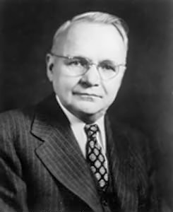
Harry Nyquist (1889 - 1976)

Worked in Bell Lab from 1917 to 1954.
Received the IEEE Medal of Honor in 1960 for "fundamental contributions to a quantitative understanding of thermal noise, data transmission and negative feedback."
Received the National Academy of Engineering's fourth Founder's Medal "in recognition of his many fundamental contributions to engineering."
Summary
The frequency response of a system is defined as the steady-state response of the system to a sinusoidal input.
It is also a sinusoidal signal, where
- The frequency is the same.
- The amplitude is \(A\times |G(j\omega)|\).
- The phase is \(\phi + \angle G(j\omega)\).